FINALLY, after many months of life responsibilities, I have been able to get back to the project! My previous installation was only temporary to test-fit the major components and aid in fabricating some new motor mounts.
I had previous concerns regarding the reactive torque and the small bolts on the Kostov motor end caps. Other installations I viewed used a band around the stator housing which was then welded and attached to motor mounts or frame mounts or something rigid. My current adapter design holds the end cap really well, but does not have extra support for the reactive torque in the housing.
The non-turbo version of the 2g Eagle Talons (and Mitsubishi Eclipses) actually had the motor/transmission mirrored in the engine bay. So I was able to find a new brace and corresponding motor mount at a wrecker. Item 32158 below.

I needed to modify the support plate so the new brace fit:

Tacked to brace for welding:

Installed to the right of the factory AWD brace:

Drilling and tapping some mount blocks:

Then test-fit with the new brace welded/bolted in place.


Next was the motor coupler and steady bearing.

Installed on the motor and in the adapter plate. This exactly matches the factory ICE flywheel and mount flange arrangement. The lower left alignment pin matches the transmission. Another is positioned on the lower right - but it ended up staying stuck in the transmission.

Installation of the new aluminum flywheel (with removed starter ring).
A nice surprise upon teardown was a Centerforce Dual Friction clutch - a nice upgrade over OEM with "reportedly" 50% more torque capacity. Just fine to handle the instantaneous electric output.


I had to assemble the transmission/transfer case and motor to position the intermediate drive shaft and steady bearing:

A difficult process with one person. I had to align the transfer case splines, clutch splines, and transmission locator pins all simultaneously. It took some patience....and some choice verbage.....but persistence prevailed!!!

I was then able to position the intermediate shaft, design, and weld the carrier bearing supports. This was done by spinning the assembly while adjusting the carrier position to ensure smooth operation of the intermediate shaft.

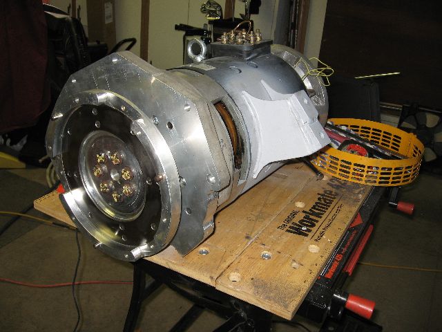
Finally, the drive system is ready for installation.

Not as pretty as the Rebirth MR2 Mount with Idler Bearing, but I think it will do just fine.

So up and at it for one last (hopefully) installation.
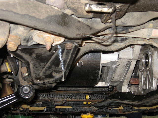
In its final resting place.

Current status is drivetrain assembled, transmission and transfer case filled, and wheels spinning on electric power!!!! Can't drive yet, but close. I have some DSM shock tower rust to take care of before re-assembling the front body.


No comments:
Post a Comment