Friday, November 1, 2013

SPECIFICATIONS

Electric Eagle Talon ICE vs EV Specifications


The turbocharged 4 cylinder was fun to drive.  The electric should easily exceed that!  Below is a comparison of the performance data.


Specification Gas Electric
Weight (lb) 3,119 3,300
Torque (ft-lb) 214 @ 3000 RPM 250 @ 0-5000 RPM
Power (hp) 210 @ 6000 RPM 238 @ 5000 RPM
Fuel Consumption Estimated (MPG : Wh/mi) 19/25 cty/hwy 300
Fuel Consumption Measured (MPG : Wh/mi) 21 Avg *
Fuel Capacity (Gal : kWh) 15.6 27.5
Theoretical Range (mi to empty : mi to 80% DOD) 328 73
0-60 Time (Published : Estimated) 6.9 4.7
1/4 Mile Time (Published : Estimated) 15 13.7
Battery Voltage (LiFePo4, 86 Cells) - 275
Motor (Forced Air Cooling) - 11" DC Series Wound
Controller (Liquid Cooled, Fully Programmable) - Evnetics Soliton1

* yet to be determined.

Monday, August 19, 2013

DSM Strut Tower Rust Repair

Well a typical problem with 2g DSM's is the dreaded strut tower rust.  Due to a design oversight, the sheet metal will rust from under the fender into the engine bay.  By the time its noticed under the hood, its usually too late.

Originally it looked like some bubbling paint:


And on further poking, prodding, and cutting....turned into this:


Prepped for surgery:


Cleaned up and box section cut out to be repaired first:


New piece cut and drilled for plug welds to internal baffle:


Welded and ground flush before top layer installation:


Top layer trimmed to fit and formed in a vice to match original angles:


View from inside the fenderwell.  Note some of the weld burnt through the original sheet metal.  The original metal was quite thin and I had some difficulty welding it.  It would probably be easier/better with a smaller 120V Mig instead of the larger 240V model I'm using.  I will be cleaning off all the seam sealer and installing new sealer.  I'll probably spray on some rubberized undercoating as well.


Close to finished, just some grinding to do:


Touching up some pits before priming and filling/painting:

It doesn't look like much, but this has been a 5-hour ordeal.  Very time consuming to clean up the rust and work back to good metal.  Then even more work to cut the new pieces and fit everything back to factory shape - or "close" to factory shape!


**UPDATE** 29 Sept 2013

Finished and painted the RH side.  The inner fender still needs new seam sealer and some rubberized undercoating.

Next up is the driver's side - which is even worse!!!


Tuesday, August 6, 2013

Motor Coupler and INSTALLATION


FINALLY, after many months of life responsibilities, I have been able to get back to the project!  My previous installation was only temporary to test-fit the major components and aid in fabricating some new motor mounts.

I had previous concerns regarding the reactive torque and the small bolts on the Kostov motor end caps.  Other installations I viewed used a band around the stator housing which was then welded and attached to motor mounts or frame mounts or something rigid.  My current adapter design holds the end cap really well, but does not have extra support for the reactive torque in the housing.

The non-turbo version of the 2g Eagle Talons (and Mitsubishi Eclipses) actually had the motor/transmission mirrored in the engine bay.  So I was able to find a new brace and corresponding motor mount at a wrecker.  Item 32158 below.


I needed to modify the support plate so the new brace fit:


Tacked to brace for welding:


Installed to the right of the factory AWD brace:


Drilling and tapping some mount blocks:


Then test-fit with the new brace welded/bolted in place.


Next was the motor coupler and steady bearing.


Installed on the motor and in the adapter plate.  This exactly matches the factory ICE flywheel and mount flange arrangement.  The lower left alignment pin matches the transmission.  Another is positioned on the lower right - but it ended up staying stuck in the transmission.


Installation of the new aluminum flywheel (with removed starter ring).


A nice surprise upon teardown was a Centerforce Dual Friction clutch - a nice upgrade over OEM with "reportedly" 50% more torque capacity.  Just fine to handle the instantaneous electric output.
Installed with the centering tool and ready for mating to the transmission.


I had to assemble the transmission/transfer case and motor to position the intermediate drive shaft and steady bearing:


A difficult process with one person.  I had to align the transfer case splines, clutch splines, and transmission locator pins all simultaneously.  It took some patience....and some choice verbage.....but persistence prevailed!!!


I was then able to position the intermediate shaft, design, and weld the carrier bearing supports.  This was done by spinning the assembly while adjusting the carrier position to ensure smooth operation of the intermediate shaft.

Finally, the drive system is ready for installation.


Not as pretty as the Rebirth MR2 Mount with Idler Bearing, but I think it will do just fine.


So up and at it for one last (hopefully) installation.


In its final resting place.


Current status is drivetrain assembled, transmission and transfer case filled, and wheels spinning on electric power!!!!  Can't drive yet, but close.  I have some DSM shock tower rust to take care of before re-assembling the front body.


Wednesday, April 24, 2013

Motor Coupler Update-2


Parts arrived - machined adapter plate, coupling hub, bearing and taper-lock.  I also found an aluminum flywheel on e-bay for a great price.  I'll remove the starter ring gear since I don't need it.


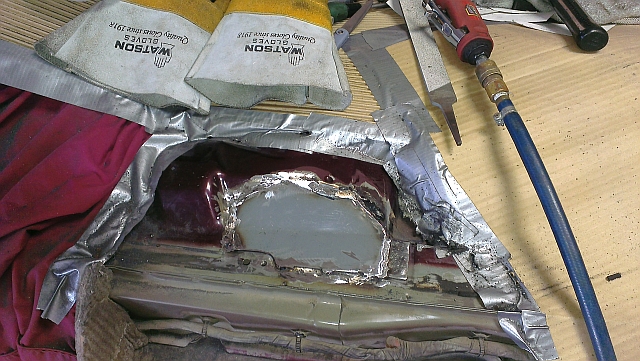
Template for trimming the motor end plate.


Trimming the motor end plate to clear the transfer case and align with the mount plate.  I must say, I thought hogging out some aluminum would be easy.  But when you are dealing with 1" and 2" thick parts - its quite another story!  Most trimming was done with a 3/4" carbide bur on my die grinder.  At a slow speed.  The aluminum tends to gum up any kind of cutting tool if the cutting speed is too fast.


Checking the motor fit.


Checking the fit with the transfer case installed.


Transfer case removed to show the profiling.


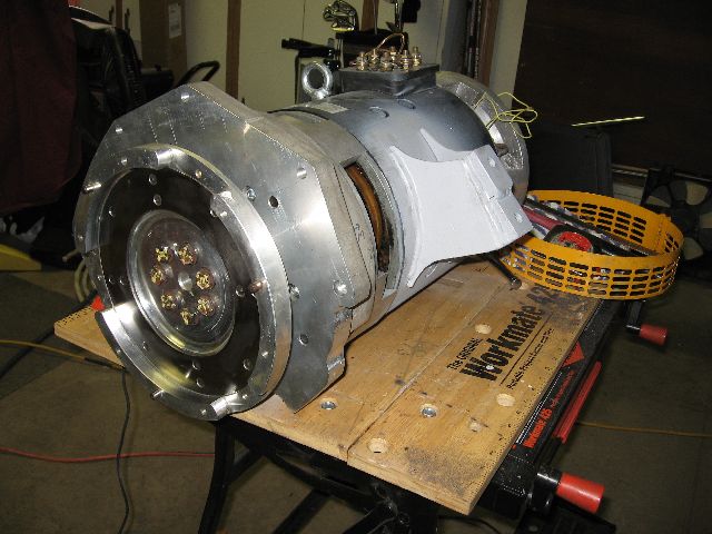
Motor and adapter plate bolted up to check fit.


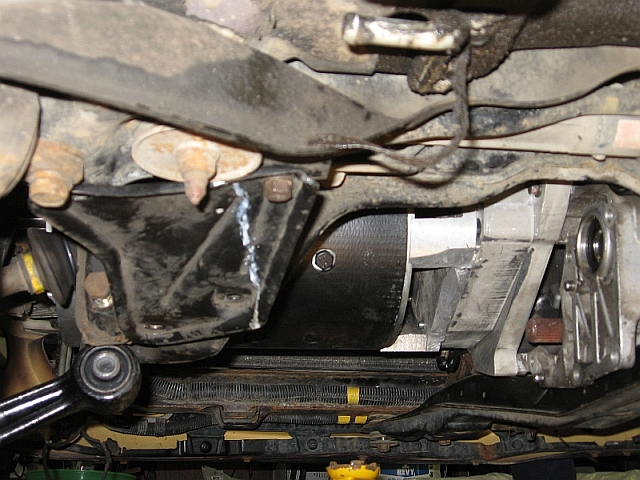
Transmission bolted up perfectly.  Temporarily installed the motor/transmission assembly to check motor mounts and clearances.


It fits !!!  And with an extra 1-1/4" clearance to the frame.  So I'll be able to use the auxiliary shaft output if I want to drive the power steering and/or A/C.


I mocked up the 4th motor mount bracket out of some styrofoam poster board. Its easy to work with and a hot glue gun firmly holds the pieces. I also incorporated a power steering mount that is similar to the factory location.


I also mocked up a torque arm.  But I don't think this is strong enough.  There are only 4 - 8mm cap screws holding the motor to the aluminum end cap.  I'm going to have to come up with some kind of banded mount.  There is no way those 4 small cap screws will handle 250 ft-lb of torque!