I was initially hoping to distribute the cells front/rear to establish an overall 50/50 weight distribution. However, due to space constraints, I'm limited to 43 front : 43 rear. With the controller placement up front, the overall "added" weight is almost a 50/50 split. I don't know what the existing chassis split currently is without the ICE components. So my ending weights will be whatever they work out to be.
Batter placement plan:

Center of Gravity (green dot) of added boxes, along with the controller, motor, and adapter plate:

Front box view and section view showing the bottom channels which will be cut with a router. Self-regulating heat cable will be placed in the channels and secured with high-temp silicone.


Box parts cut, bent, and cleaned after plasma cutting:

I used a "flapper" style grinding disc on the aluminum. Regular grinding discs plug immediately and are rendered useless:

Tacking the frame and sides together:


Rear box:


Test fit of the rear box --- just barely slides in between the sub-frame rails!

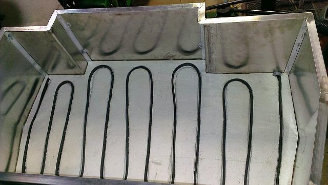
Self regulating heat cable installation:
Junction box for heat cable entry:

Covered with rubber mat and beginning insulation install:

PVC conduit painted orange to designate HV wiring (follows exhaust pipe path):

Massive crimper for 4/0 and 2/0 HV cables:

Rear cabling crimped and sealed (dual-wall heat shrink) and ready for install. Note the additional 4 batteries on the RH side. These were originally planned to sit at an angle over the rear diff (see CAD pic above). However, due to the body curves and clearance problems, I was not able to fit the box in as originally designed. This is plan B - the cells will be covered with a formed polycarbonate sheet. I used the available space to mount the junction boxes and Blue Sea disconnect switch. The boxes will contain the rear pack fuse and EV Display sensor board. In addition, the charger negative lead will be connected inside the EV Display box to capture energy transfer during recharging.


Front cabling crimped and ready for box install and cell wiring. I need to finish tidying the wiring and connecting the vacuum lines (for power brakes) before installing the front box - as it covers everything under the hood. I designed the front box to be removable even after the cells are installed. However, its easier at this point to finish the underlying details. The aluminum cross arms will support the front box. They are bolted into the frame using heavy duty rivet nuts. The driver's side is bolted rigid. The passenger side incorporates a slip-joint to compensate for the thermal expansion difference between the aluminum and steel. I decided to include this feature since the braces are fully constrained between the rails. The rear braces hang below the frame rails so this feature was not necessary there.

Motor wires attached to the controller:

To be continued...
Great blog! I've wondered myself about converting my gst to EV. Keep at it!
ReplyDelete